MNC Magnetostrictive Liquid Level Transducer (Analog)
Click:

MNC1 type Magnetostrictive Liquid Level Transducer (Analog)
DESCRIPTION
1.GENERAL
The magnetostrictive linear displacement transducer is a contactless linear position sensor designed for accurate absolute position measurement of displacements up to 5000mm. By adding a magnetic float, The magnetostrictive linear displacement transducer is capable of liquid level measurement.
Utilizing magnetostrictive technology, The magnetostrictive linear displacement transducer measures the distance from a predetermined point (Zero point) to the magnetic field produced by a movable permanent magnet. Because the moving magnet’s position is coupled by the magnetic field, The magnetostrictive linear displacement transducer requires no mechanical contact between parts that would cause friction and wear. The magnetostrictive linear displacement transducer provides an absolute output, therefore, no data is lost if power is interrupted. The magnetostrictive linear displacement transducer offers modular construction, flexible mounting configurations and easy installation.
2. Notices Before Installation
It is recommended that carefully reading this user manual and following the installation guidelines before installing transducer:
1. Ensure the packaging neat,and also confirm whether the parts are complete.
2. Avoid installing in a location where exposes to the excessive shock, vibration, pressure or over high or low temperature.
3. Keep away from the ambient conditions such as the condition of being flammable, detonable, erodent, steamy, liquid and any chemical reaction environment. Unless the electronic head unit is waterproof, do not put the hexagonal base into the liquid.
4. It is better that the power is used alone. The power cannot exceed the range of fluctuation(+24VDC±10%,±15VDC±10%), but at least can provide 150mA load current.
5. The transducer connects with the power independently before installation. Move the float in hand to check whether the transducer work well, then install it if no problem.
6. The transducer wire must be avoided the high-power equipment and high-current cable affecting the work.
7. Electrical interfaces should be tighten, to prevent the water entering the transducer.
8. It should be thoroughly clean the residual liquid that attached the transducer for the used product.
3.Specifications:
| Measured position | Modbus—1~3 position or 1~5 temperature points Analog—1~2 position |
| Operating voltage | |
| Measured position | Modbus—1~3 position or 1~5 temperature points Analog—1~2 position |
| Operating voltage | +24VDC±10% ;±15VDC±10% |
| Outputs |
0~5VDC 0~10VDC -5~+5VDC -10~+10VDC 4~20mADC ModBus Hart |
| Range | Rigid structure:50~5000mm Flexible structure:4000~20000mm |
| Load characteristics | Current output:Load Resistance 600Ω(Max.) |
| Voltage output:Load current 2mA(Max.) | |
| Operating Current | <70mA |
| Operating temperature | -40~+85 ℃ |
| Storage temperature | -40~+100 ℃ |
| Non-linearity | <±0.01% F.S.or 1mm max. |
| Repeatability | <±0.002% F.S. |
| Resolution | 16bitD/A ,0.1mm |
| Hysteresis | <±0.002% F.S. |
| Temperature coefficient | <±0.007%F.S./℃ |
| Zero range | 100%F.S. |
| full-scale range | 100%F.S. |
| Update time | depends on range,but less than 20ms |
| Probe material | A.0Cr18Ni9(304) B.316SS |
| Housing material | A.0Cr18Ni9(304) |
| Mounting | A.threaded connection B.threaded flange |
| Cable | integral cable, mating connector, integral connector |
| Sealing | Housing:IP65,Probe IP68 |
| Explosion Proof | Exd ⅡBT5,Exia ⅡCT6 |
Note: The F.S. is short for Full Scale.
4. Product Structure Diagram
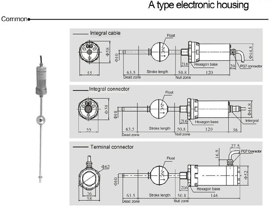

1.Sensor rod 10mm diameter for stroke length within 3 meter, 13mm for over 3 meters, 14mm for sensors with temperature measurement.
2.Electronic housing material: Aluminum for common type with integral cable and integral connector, stainless steel for terminal connector and flame-proof type.
3.Recommend A type electronic housing for over 3 meter stroke length.
5.APPLICATIONS
The magnetostrictive linear displacement transducer is ideal for measuring the position of moving machine parts in applications mcluding hydraulic cylinders, injection molding equipment, machine tools slides, heavy duty robots, lumber mills, woodworking machinely, automated material handing systems, and a variety of motion sensors. The magnetostrictive linear displacement transducer is also ideal for measuring the level of static liquids in storage tanks or reservoirs containing nonflammable, noncorrosive, and nonhazardous liquids.
6. Notices Before Using
l keep the transducer straight and less than 3°deflects from the standard of the vertical position .
l The cable joint is treated by waterproof, moisture-proof.
l The electronic components of transducer, that splash but not be flooded.And not be flooded to the base of the electronics housing.
l It must not share the power supply with other actuators such as pump motor, electric power . And strictly abides by state of transducer’s introduction .
l It must not dismantle the field wiring when woking. If the vessel or the electrical construction (e.g., welding, pump motors, etc.) is working,it should stop use the transducer, and dismantle the ground of the transducer, and apart from the ground and the vessel.
7.INSTALLATION
7.1 Notices Before Installation
It is recommended that carefully reading this user manual and following the installation guidelines before installing transducer:
1. Ensure the packaging neat,and also confirm whether the parts are complete.
2. Avoid installing in a location where exposes to the excessive shock, vibration, pressure or over high or low temperature.
3. Keep away from the ambient conditions such as the condition of being flammable, detonable, erodent, steamy, liquid and any chemical reaction environment. Unless the electronic head unit is waterproof, do not put the hexagonal base into the liquid.
4. It is better that the power is used alone. The power cannot exceed the range of fluctuation(+24VDC±10%,±15VDC±10%), but at least can provide 150mA load current.
5. The transducer connects with the power independently before installation. Move the float in hand to check whether the transducer work well, then install it if no problem.
6. The transducer wire must be avoided the high-power equipment and high-current cable affecting the work.
7. Electrical interfaces should be tighten, to prevent the water entering the transducer.
8. It should be thoroughly clean the residual liquid that attached the transducer for the used product.
7.2 Installation Method
Notes: Float installation direction:NC is up,ON is down.(see Page.4)1.Flange or special flange must be ordered for the level measurement of wet tanks. (Figure 1)
2.Optional Float Kit FK-1 is recommended for installation of units when measuring unsealed tanks. (Figure 2)
3.Optional Float Kit FK-2 is recommended for installation of units when measuring sealed tanks. (Figure 3)
a) Process a thread holes in the pot cover of the transducer.
b) Connect turnbuckle with the transducer.
c) According to the direction to operate
d) Fix reataing collar at the end of the scale of the transducer, the side which near the float close to scale.
e) With ptfe for filling in the place of the turnbuckle.
f) Take the transducer into the tank.
4.Optional Float Kit FK-3 is recommended for installation of units when measuring the tank which its height could be adjustable. (Figure 4)
a) Put the union joint into the transducer, and adjust the length well.
b) Connect turnbuckle with union joint.
c) According to the steps c, d, e,f from the Installation fashion 3.
5.Optional Float Kit FK-4 is recommended for installation of units when it is flexibility liquid level transducer. (Figure 5)
a) There need more than 3 persons to install the flexibility liquid level transducer.And the bending radius of flexible conduit should not less than 500mm.Don’t install with electric.
b) Put the adjustable fitting into the rod.
c) Put the transducer into the center hole of flange , there is always a person keep flange stable in installing.
d) Put the float on.
e) Install the heavy hammer and reataining collar from the end of the transducer. Don't slide items such as float in the installation.
f) Put the asbestos gasket in the entrance.
g) Insert the transducer from the entrance.
h) Move the float to the hammer in order to prevent the float freeing fall.
i) Put the transducer and the float to the bottom of the tank. And install the flange connecting well.
j) Take up 5-10 millimeter when the transducer get to the bottom of the tank,which may get the conduit straight.
k) fix the adjustable bolts, and let the transducer stable.
l) confirm the attributes and polarity of the wire.
m) properly connected to each wire, record the numble of the tank and the color of wire.
7.3.Actual Level Adjustment
Because the actual status of the storage tank commonly is different from the design,and the end of the transducer should keep a certain distance to the bottom of the tank when installation,there is some error between the aritificial measure and the machinal measure. In normal, the error is a fixed value. In order to the storage tanks in the consistency of the metrological verification, take the zero from aritificial measure as standard and correct the error as fellows:
1、 Artificial measure should operate by the professional. The ruler that use to measure shall be qualified.
2、 artificial measure should strictly abide by the rules.
3、 The depth of the measured medium should be enough for the float to the top.
4、 It should be measured several times and take the average for the standard (measured in liquid surface,keep calm), and the result should be compared with the data that the system simultaneously detect.The error is the correction.
5、 The zero of liquid surface and interface should be revised separately.
6、 Put the zero correction of liquid surface and interface separately into computer and correct, then compared with the measured value until Artificial measure and the output value of the transducer are the same.
Installation fashion 1 (Flange Connecting)